Most musical instrument (i.e., anaerobic guitar) amplifiers still use vacuum tubes, in large part because tube amplifiers saturate slowly, giving a ``warm-sounding'' distortion, while transistor amplifiers cut off sharply, so they have unpleasant high-frequency components in their output.

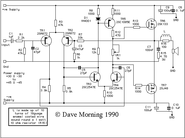
This is a schematic for the Mosfet amp. Following are the comments of the creator David Morning , back in 1991 when he sent it to the future homeboy of the Stammtisch Beau Fleuve. Any errors here are the homeboy's fault.

Dave Morning's gloss:
The design is based around the Hitachi design and, as such, uses Hitachi Mosfets and transistors. I believe these are difficult to obtain in the US, (They're 10 a penny [in the UK]) but IR do a range of Mosfets which should work fine. The specs for the two are:-

2SK133
	Drain-Source voltage    Vdsx=120
	Gate-Source voltage     Vgss=±14
	Drain Current           Id=7A
	Reverse Drain Current   Idr=7A
	Power Dissipation       Pch=100watts

2SJ48
	Drain-Source voltage    Vdsx=-120
	Gate-Source voltage     Vgss=±14
	Drain Current           Id=-7A
	Reverse Drain Current   Idr=-7A
	Power Dissipation       Pch=100watts
The IR data book suggests the IRF220 range as a cross reference for the 2SK13X range so I'd suggest an IRF221. The 2SJ4X is cross referenced as IRF923X range. I'd suggest IRF9231 as the equivalent. There's one major fly in the ointment...the pin-outs :-( Looks like this...
    Hitachi               IR
      o                    o

drain  gate          source gate	
   o     o              o     o

      o                    o

   Case=Source        Case=Drain
So the drain and source connections are swapped over. Isn't a serious problem but it will mean some juggling about with the foil routes (good practical exercise for a student :-) )
The bipolars are much more straight forward. Just make sure that they've got reasonable Hfe >100, can cope with the full supply and are reasonably low noise.

SUGGESTED TWEAKS:-

  1. If it is intended to use the amp for an electric guitar, the RC network C7, R15 MUST be removed. R15 will fry otherwise as guitars running the amp into overload or indeed even the pre-amp generates so much hf that C7 becomes effectively a short and virtually the whole output voltage swing appears across R15. A quick ohms law with around 20 volts across a 4.7 load will give the power dissipation across R15 will give...err...rather a lot :-)
  2. Reducing global feedback. Again this is related to guitar (and indeed hi-fi) amps and drops the ``audio hysteresis'' effect. R6 controls the global feedback. The gain can be dropped by introducing more local feedback at the various stages. Increasing R10 is a likely contender but watch the bias settings, you may have to compensate by adjusting RV1 or R11.
  3. Switch on thump. This is a real pain with Mosfet amps but it can be cured quite easily. Essentially the output devices switch on far too quickly causing a large transient voltage at the output stage. Holding off the respective gates for a short period and bringing them up slowly will help. A 100ohm resistor isolating the supply to the output stages from the input stages and a small 100µF capacitor will bring up the gates at a bit more reasonable rate. It also has the bonus of improving the ripple rejection of the drive stages. Looks like this..
    V+---------------|100ohms|------------>drive stage supply
             |                    |
           TR6drain               = 100µF
                                  |
           TR6source             GND
             |
    LSpkr----|
             |
           TR7source
    
           TR7drain
             |
    -V---------------|100ohms|------------>drive stage -ve supply
                                  |
                                  = 100µF
                                  |
                                 GND